Design of our Water Rocket (Dhravam 1.1)
We have almost finished the design phase of our Water Rocket, and today we'll be seeing about the following:
- Our design of DHRAVAM 1.1 in detail!
- Each part of the design will be addressed and the reasons for that particular design in that particular way will also be explained!
- A few images of our rocket and the construction of it!
- Simulation details and results of it!
- And many more information about the project!
So without any further delay, let's dive into the design :)
DESIGN
DESIGN
The design of our rocket is as illustrated here.*#

*Components not to scale
#Fin design changed
This is the 2-D design. We'll be using 3 identical bottles, each of 2.25 litre volume. Among them, two bottles will be joined together and they will function as the pressure vessel. Thus, the volume of the pressure vessel will be 4.5 litre. The third bottle will be the payload bay, more about this in a minute. We'll see about each part of the rocket in detail.
PRESSURE VESSEL
Obviously, the pressure vessel is the most important part of the rocket. It's at this part of the rocket, where the fuel is filled up (water and pressurized air, in our case). So in our pressure vessel, we'll be joining the two bottles in the way depicted below.
This is an illustration of the process. I'll describe the process in detail. The way we are joining is as follows:
- First, we'll make a hole at the centre of the base of a bottle and then make a hole at the centre of the lid of the other bottle.
- Then, we'll stick the lid, which has a hole, to the base of the bottle, which has a hole as well.
- Then we'll seal the edges of the joint permanently using something like M-Seal.
- Then we can screw the second bottle to the lid which is joined to the first bottle.
You might ask, why we are joining in this complex way, making holes in them carefully so that the structure doesn't damage and sticking them together, instead of easily cutting their base parts and joining them in the way shown below: (I am saying this because this is the most common joining multiple bottles in a pressure vessel of water rockets!)
And the reason is simple. Did you notice that we are using a soda bottle, i.e. carbonated drinks bottle? That's not a coincidence, but there is a reason for it. Comparing to normal water bottles, carbonated drinks bottle can withstand a lot more pressure. And the part that helps the carbonated drinks bottle to withstand more pressure is the bottom part of the bottle, which has several curves in it. The curves help to distribute the pressure all over the base. If the base part is flat, like the water bottles, then the pressure won't distribute equally so the bottle will be damaged.
The reason for carbonated drinks bottles designed to withstand more pressure is that they are filled with juice and then they are filled with carbon dioxide gas, as the name carbonated drinks suggests. The carbon dioxide in them keeps rising so the pressure in them keeps rising. That why when we open the seal in them, we get a fizz. Water bottles don't need to withstand pressure at all, that is why they aren't designed in that way.
OK, back to our rocket. As you might know, the pressure in water rockets play an important role. The more the pressure, the better the performance. So as we need to improve the performance, it is better to use soda bottles so that our rocket withstands more pressure and performs well.
As we had seen, the bottom part of the carbonated drinks bottle is the part that helps hold more pressure. So if we cut off the bottom part, then it won't withstand higher pressure, which is what we don't want in our water rocket.
You might also ask, why we are joining with the lid, rather than joining directly. And the advantages/disadvantages of these two methods are as follows:
JOINING DIRECTLY
- We need to make a larger hole in the base of the first bottle and it should be in a perfect shape, which is a little hard and even a small mistake will damage the bottle.
- It's also not easy to stick them directly as the surface area on the mouth of the second bottle is not large enough, as shown below:

The "Glowing" ring depicts the surface area available for sticking directly
- So in order to join them, we need to make a hole at base of the first bottle large enough to screw the mouth of this bottle deep enough so that it is stable, which is hard as well.
- After joining them, it's really hard to replace any the bottle, if it has got damaged.
JOINING USING A LID
- If we join using a lid, then it isn't necessary to make a large hole in a perfect shape, because we would have enough surface area to stick them directly. I forgot to take a photo of the lid, which I had cut, before sticking it into the bottle. But I can say in text, about how much surface area is available for sticking. It can be visualized through the below video, which I made.
- As you would have seen, it is easier to stick with a lid, as it has more surface area to be glued to the bottle. And, the contents of the second bottle should flow to the first bottle and the flow should be as smooth as possible. The larger the hole, the smoother the flow. But in this case, the hole would be smaller in the lid, than the mouth, as it is depicted in the video. But the difference is very small so we can ignore it!
- Another advantage of joining together using a lid is that we can replace a bottle of the pressure vessel, if any of it has got damaged.
OK, now I'll show some images of the components of the joint that we had made, and some other images too.

Here, I have marked the largest hole that we can get from this lid. Could you see that there is a little "ring" in the lid that I had marked, which is near to the threads? The area inside the ring is the maximum area that could be cut to make a hole in the lid. If we go beyond that, then the lid would break and we won't be able to properly screw the bottle to it.

This is how it looks when the lid has been cut and glued to the bottle.

This is the joint. I had sealed the edges of the joint using M-Seal.

Pressure vessel when joined
OK, so now we have joined the two bottles, then we have to cover it so that the surface is plain. You would have witnessed that the bottle itself has many curves in them. We can make them straight by the following method.


The red rectangles demonstrate "tapes"
OK, now the pressure vessel part is almost over, now let's go to the payload bay.
PAYLOAD BAY
This is the second important part of our rocket. As the name suggests, this part houses the payloads of our rocket. The payloads that will be carried by our rocket are the parachute and the avionics. Our current plan for making the parachute is, by removing the sheet from an old umbrella, stitching shroud lines and shock cords into them and then attaching it to our rocket. Our current design for it is as shown below:

*A raw design, Components not to scale
I've attached a video below, in which I'll explain the components of the payload bay and there will be a demonstration of the parachute ejection system.
The test video of our Parachute Ejection System is attached below:
The parachute that we'll be using is of roughly 1 metre diameter. The canopy of the parachute will be a sheet removed from an umbrella, and then we'll stitch the shroud lines.
The avionics of the rocket will be explained in a separate article.
We'll see about the fin design in the simulation section, as it was generated using the simulator.
SIMULATION
OK, now let's see about the simulation part of our rocket. We did the simulation mostly for checking the design characteristics and stability. We also wanted to do simulations about the propulsion characteristics, but unfortunately, most of the simulators are for solid motor rockets, so we estimated the propulsion characteristics by solving equations for it. We also tried to simulate the propulsion characteristics of our rocket, we'll see about them in a separate article regarding propulsion, as this article is mainly about design.
We used OpenRocket Simulator for checking the aerodynamics and stability. OpenRocket is a Java based simulator and if we download from their own website, the software comes in .jar format. I feel comfortable with the .exe format software, so I downloaded the OpenRocket Simulator from GitHub.

OpenRocket Homepage
OpenRocket is only made for solid motor rockets, so I used it only for checking the aerodynamics and stability of the rocket. I have put them altogether into a video attached below. It has all the parameters that we checked in the simulator.
Now, we can see the images that we generated in the Photo Studio:

This is the image with mountains as background
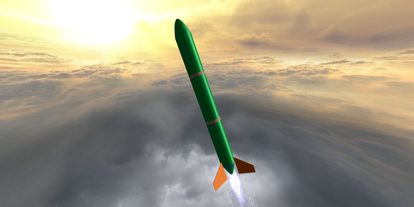
This one has clouds as background

This one has meadows as background. Isn't it natural and realistic?

This one is in orbit!!

This one has dark clouds as background
We will update our progress in our projects regularly in our social media accounts and sometimes in blog articles like this. We won't write articles just about our projects, but we also write interesting articles regarding aerospace. An article regarding the propulsion and avionics of DHRAVAM 1.1 will be out soon! Stay tuned:)

Congrats to the Aerospacizm team for your hardwork and dedication to making this wonderful post.DHRAVAM is an awesome rocket. Looking forward to this launch!!!
ReplyDeleteThanks ☺️
DeleteGreat work guys, looking forward for the upcoming articles, It's amazing to see you guys taking interest in rocketry and educating the masses about it. Excited for the first launch of this rocket, keep us updated..!!
ReplyDeleteThanks for the compliment and sure will keep you updated
DeleteThe article is well written and the details are explained precisely. Looking forward for future works :)
ReplyDelete